Today, the morn of the 12th of October 2020 brings the entire city of Mumbai to face a power cut. With draining batteries in my laptop and mobile, I face the challenge of taking up one of the possible activities from my pending to-do list! – Stacked Piezo Disk testing. The Aim here being to test if stacking the piezo disks can give a better performance.
But my pre-task lies in how to stack them? How to add a cable between two layers and have the layers flush against each other.
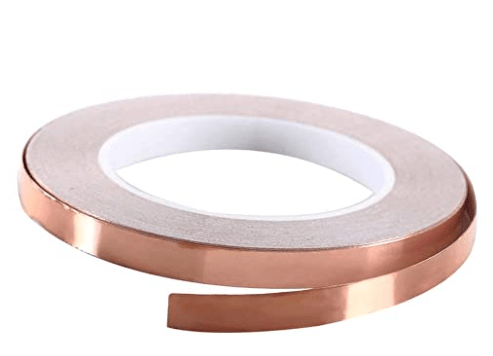
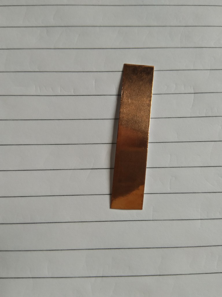
Previously I would have used this copper conductive tape, since that is all I had for such a job.
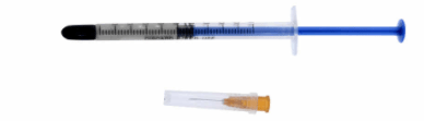
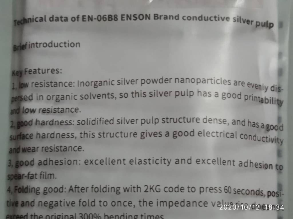
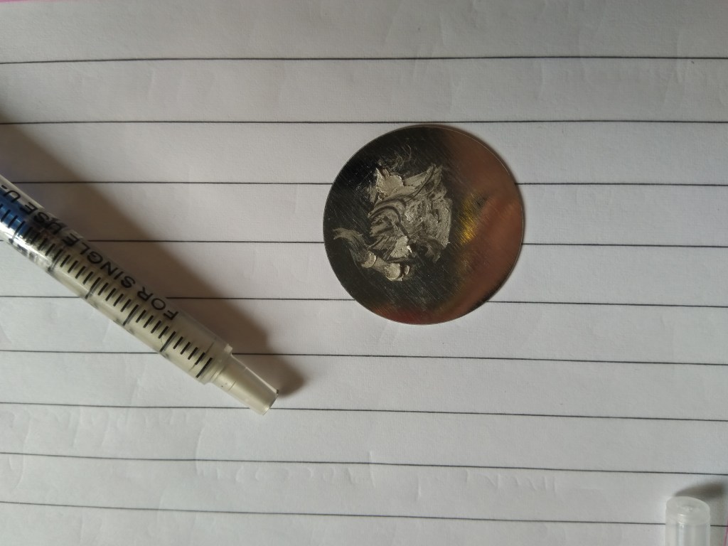
But today I also have some silver super conductive glue called “EN – 06B8 Enson Brand Conductive Silver Pulp”. (pretty expensive – I must add Rs. 1,800)
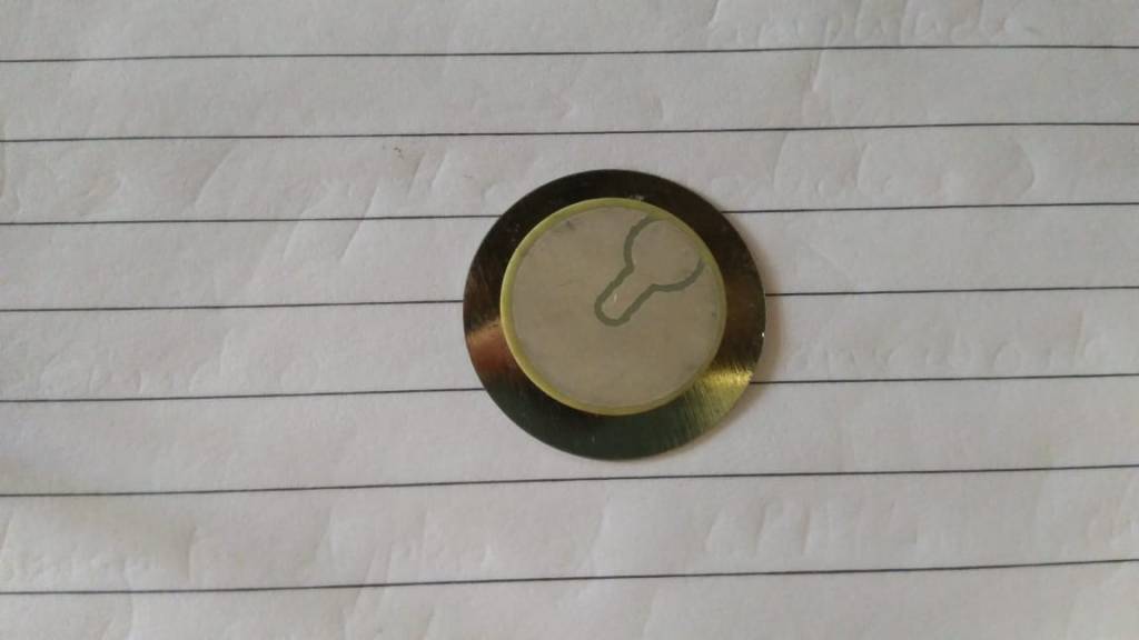
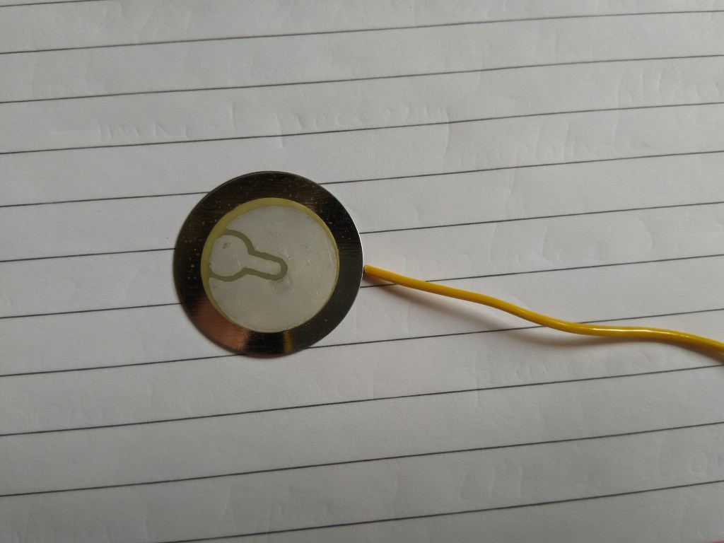
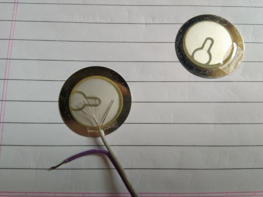
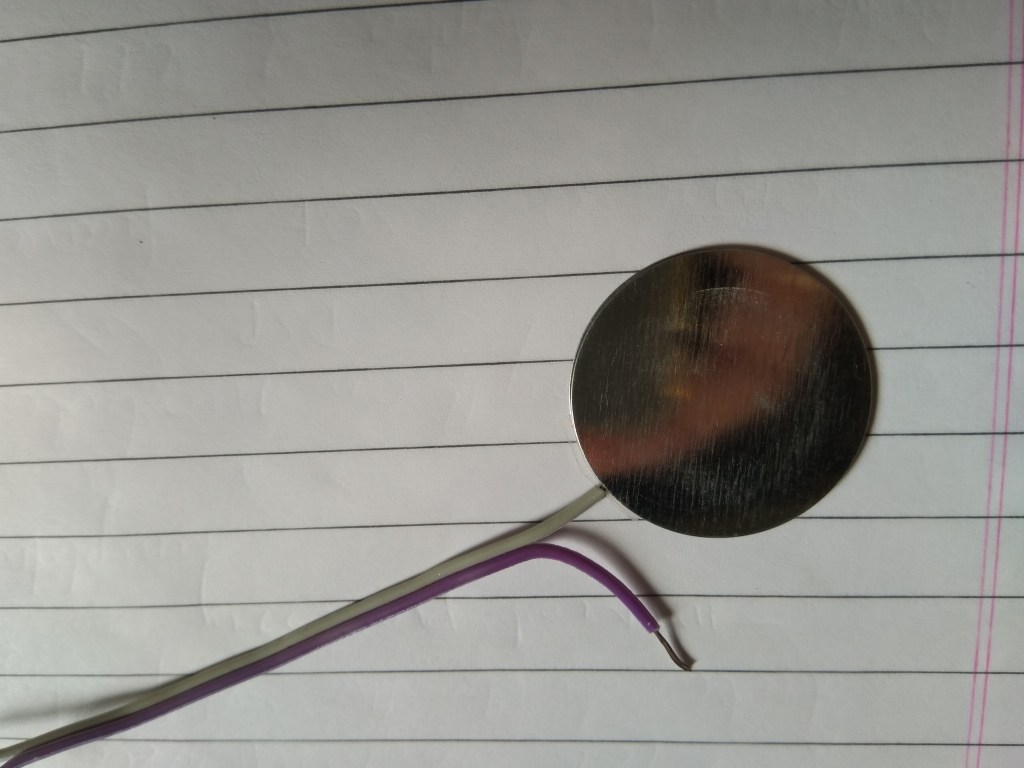
And here’s how a simple piezo disk looks like. ( just received these from Amazon)
So I open this pack of Silver conductive glue, this syringe with a needle and cap, which made me expect the consistency of this sliver “pulp” to be liquidly, but it was really thick. I disconnected the needle head and used it as is. (You can see the consistency, looks like a pencil tip)
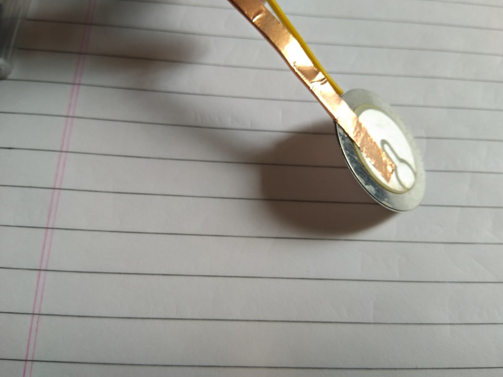
In the first case I am making the 2 shields / metal plates face each other. A multi-strand cable is used, and the strands are opened up to reduce the distance between the plates.
The 2 disks are now stuck back to back.
Now using the Copper (Cu) conductive tape to make the second electrode. (You can solder on this electrode coted side of the piezo, but the coating tends to leave the piezo material and the electrode film gets disrupted. The temperature of the solder gun needs to be reduced to do this efficiently.)

The Cu tape is split to make the short for the two electrodes of the 2 piezo disks. The paper below this Cu tape is only partially removed in order to prevent shorting with the “shield / metal plates”, later a wire will be soldered to the other end of this Cu tape.
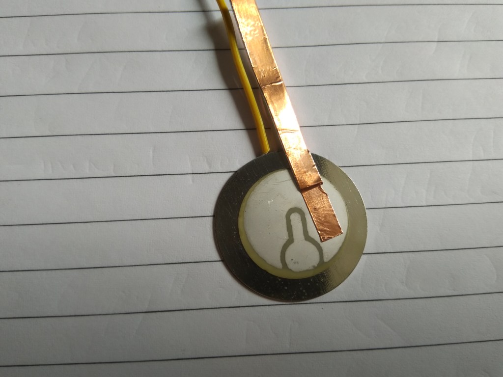
Here the wire becomes the COM terminal or the HV- (high voltage negative) terminal while the Cu tape becomes the HV+ (high voltage positive) terminal.
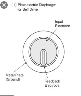
Now taking the second case where we stick the 2 electrode faces. (the small electrode is the feedback pin. In this case I will short this with the main electrode , making it just one electrode, since my driver circuit does not have provision for this type of feedback arrangement.)
Tape a part of the disk in order to prevent any shorting.
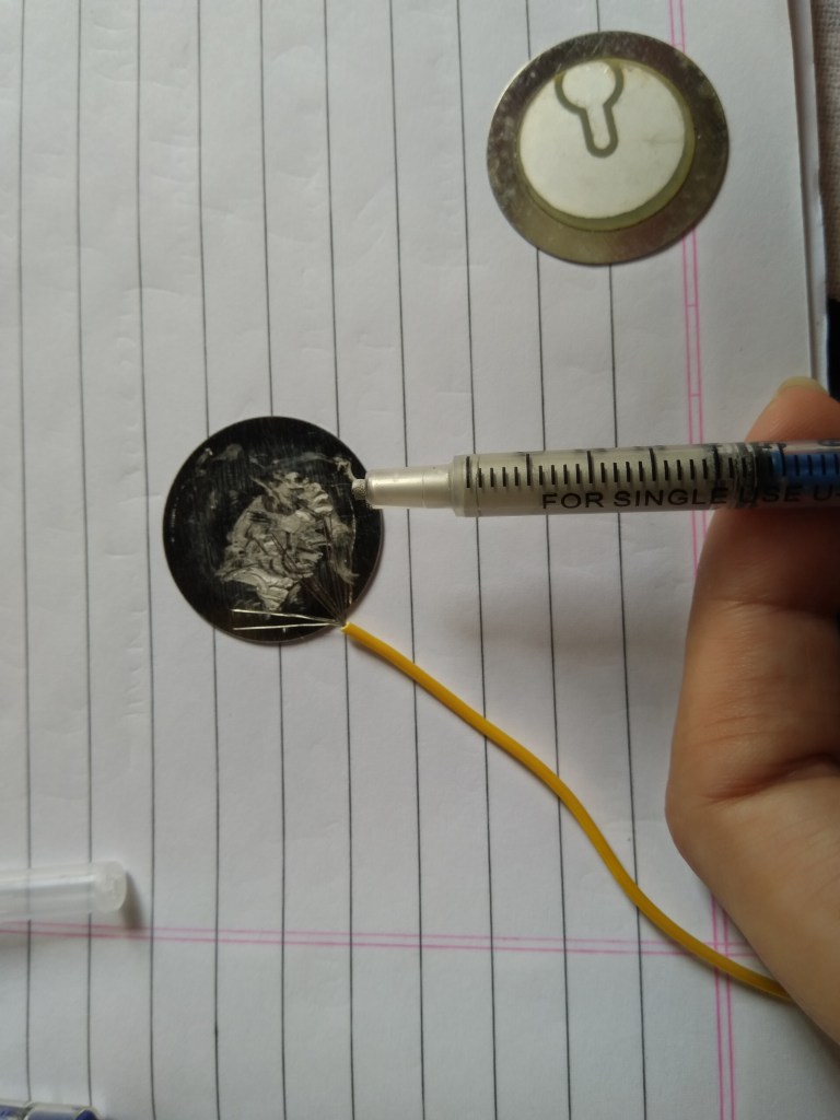
Then apply the Silver conductive glue.
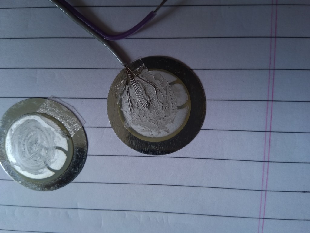
This Silver conductive glue appears to become softer and easier to spread out after about a minutes exposure to air.
Here I have shorted and closed both the electrodes with this Silver conductive glue.
Pressure needs to be applied for a minute to hold the 2 disks in places.
These now need to be left to cure for atleast an hour.
In case you are wondering why the second lead is left open. It will be soldered later. There is no issue in soldering on the metal plate/shield.
Now in this second configuration, the grey wire goes to HV+ ((high voltage positive) terminal while the purple one goes to the COM or the HV- (high voltage negative) terminal of our piezo driver circuitry.
